 EN












Grinding wheel factory layout: checking material flow, holding areas and maintenance space
Published
Review resin wheel line transfers, oven-side carriers, inspection holding areas and component-removal space using schedules and operating scenarios.
A grinding wheel workshop plan may show neatly arranged machines but leave nowhere for waiting blanks or returning empty carriers. Follow one batch through the plan: where is mixed material handed over, how are formed blanks loaded, where do products wait for the oven, and how do empty carriers return? Then check the space needed for changeovers and maintenance separately. This reveals whether the gaps between machines are usable.
For resin-bonded grinding wheel and cutting disc lines, first select representative products and their actual production routes. Show equipment, carriers, operating movements, product status and maintenance envelopes on the same plan. Identify normal-production occupancy and the areas to clear for changeovers or shutdown maintenance. Overlay activities that will actually occur together.
This article covers preliminary layout review. Equipment clearances, aisles, foundations, ventilation and fire protection need confirmation by the relevant specialists using equipment documents, material information, building conditions and local project requirements.
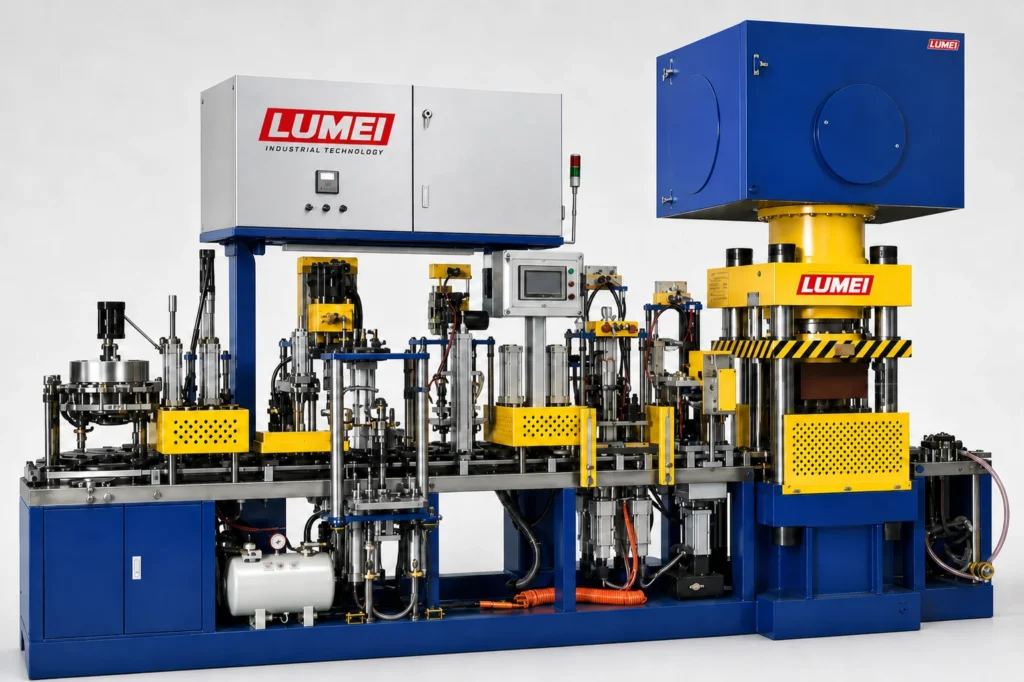
1. Define product routes before arranging machines
The same equipment list does not necessarily produce the same material flow. Flat cutting discs and depressed-centre grinding discs may use different tooling, supports and loading arrangements. Order mix and changeover frequency also affect storage for molds, reinforcing mesh and carriers.
Before drawing the layout, list the products planned for the current phase, shifts, batch definitions and intended process routes. If equipment scope is still open, use the machine selection and product-range review to organize inputs. This helps avoid discovering tooling or auxiliary-equipment changes after layout approval.
For each representative product, mark material preparation, mixing, forming, curing and the finishing, inspection and packaging actually required. One flowchart should not become the fixed route for every wheel. Where applicable, identify destinations and return points for rework, additional inspection or external evaluation.
Arrange equipment around the confirmed process and transfer methods. Straight, U-shaped and zoned layouts are options to discuss; their shape alone does not establish suitability.
2. Draw the people, materials and containers involved in each transfer
For a transfer from mixing to forming, draw more than an arrow. Identify the container, quantity per trip, handover point, any stopping position and the return route for empty containers.
Do the same for formed blanks: from the collection point to the specified carrier, is turning, changing hands or rearrangement needed? Support and handling must follow the product's process requirements. A shorter route does not justify unverified stacking or transfer methods.
Overlay material replenishment, empty-container return and personnel routes on the main flow plan. Look for crossings: must the person replenishing mesh pass through a position occupied by a trolley? Does an empty trolley obstruct the next batch's handover point?
Swipe horizontally to view the full table.
| Transfer point | What to add to the plan | Question to check on site |
|---|---|---|
| Mixing to forming | Filled containers, handover point, empty-container destination | Do material delivery and component replenishment compete for space? |
| Forming to loading | Collection point, carriers and loading workstation | Do placement and handling meet blank-support requirements? |
| Before and after curing | Oven waiting, unloading and process-required cooling positions | Do door opening, loading, unloading and transport conflict? |
| Inspection to packaging | Pending-inspection and evaluated products, packaging handover | Can different product statuses be identified and moved under control? |
Number transfer points and link them to containers, handling methods and operating envelopes. Where routes cross, check timing and actual occupancy to decide whether activities can be separated in time or positions need changing.

3. Review oven-side carrier positions against the schedule
Continuous blank output and batch curing need a separate coordination check. If forming continues while the next oven load cannot be accepted, waiting products need a defined place. Leaving them in an aisle does not resolve the process interface.
Build a timeline for the intended schedule: forming starts and stops, cumulative blanks, planned loading, unloading, process-required cooling and carrier return. Do not enter only curing hold time. Include other periods occupying the equipment and carriers; assess which activities can overlap for the actual equipment and production arrangement.
Choose points when occupancy changes, such as loading, unloading or shift handover. Record the initial quantity awaiting transfer in the area, additions during the interval and actual transfers out. Check closing quantity as “opening quantity + additions − transfers out”. Record the destination of isolated or otherwise relocated products too, keeping the counting boundary consistent.
Convert each batch into carrier requirements using the permitted support arrangement. Combine spare loading capacity across batches only where process and batch-control rules allow. Do not add all products together and assume every trolley can be filled. Count empty carriers, carriers being loaded and carriers awaiting cleaning at their actual locations; count each carrier once at any given time.
Compare occupancy at these points to find the state needing the most simultaneous positions. Check parking, turning and loading/unloading envelopes as well. Carrier footprints account for only part of the space.
For example, in a hypothetical schedule the next load is ready and waiting, carriers from the previous load are still cooling or awaiting unloading, and the press continues producing blanks. These occupancies may overlap. Draw their locations separately rather than assigning all three states to the same blank space. Actual overlap must be established from the project's schedule and carrier records.
A shorter route does not allow arbitrary reductions in waiting or cooling conditions. If the area is insufficient, review scheduling, batch size, equipment provision and carrier circulation. Stacking, blank waiting conditions and loading arrangements must still meet the confirmed process requirements.
4. Give pending-inspection and abnormal products a defined location
A “finished-product area” containing uninspected products, samples awaiting review and released products is difficult to control through verbal handover alone.
Draw normal flow and abnormal-product handling separately. For products awaiting inspection, review or further movement, specify locations, identification, batch links and conditions for removal. Separate areas, dedicated racks or another controlled arrangement should match the site's quality management system.
Consider results pending across shifts: can the next shift find the records for samples and batches left behind? After additional sampling, can the remaining products still be identified? Could products that have passed blank inspection enter a stage requiring finished-product release?
The mold-change restart and batch-record guide explains how these records connect. In the layout, provide actual holding conditions for pending actions and use the relevant quality procedure to decide when products may move onward.
5. Extend the maintenance envelope to include component removal
A gap around the machine does not establish maintainability. Opening doors, withdrawing parts and using tools or handling equipment may require space beyond the machine footprint.
Request installation and maintenance documents for the proposed configuration. Check service faces, cabinet and guard-door opening envelopes, specified dismantling directions and component-removal routes. Include tooling trolleys, mold racks and changeover work positions. Distinguish permanent service clearances from working areas that can be cleared during shutdown. Where a location is shared between scenarios, confirm clearing, isolation and restoration conditions without occupying routes that must remain unobstructed.
For example, an area may accommodate a person but leave no room to turn a removed component for transport. Alternatively, an open cabinet door may overlap a replenishment position. The first case needs a removal-route check; the second needs an assessment of simultaneous work and whether the planned work arrangement can be implemented.
Review power, compressed air and other required interfaces at their actual positions, together with cables, pipework and professionally designed ventilation. An equipment-position drawing does not complete foundation-load, environmental-control or fire-protection design. These depend on the materials, processes and relevant specialist design, rather than one universal value in an article.
6. Walk through three scenarios before freezing the plan
Review normal production, a planned changeover and a batch awaiting further assessment. Follow each scenario from material entry to product handover and empty-carrier return, beyond the immediate machine area.
For normal production, check replenishment, collection, loading/unloading and return. For a changeover, check old-mold removal, new-mold delivery and specified operations. For pending assessment, check whether held products occupy normal circulation positions.
On drawings, use the same scale for the building, equipment and carriers. Include columns, door openings and relevant clearances. To assess actual pushing, parking and turning, mark out a suitable area at 1:1 scale and use real carriers or equal-envelope models. Gaps in a reduced-scale drawing do not directly establish workable personnel space.
For equipment not yet installed, use supplier information for operating and maintenance envelopes and necessary height details. Separately check component lifting, hoisting and overhead obstacles that a floor model cannot represent. Use mock-up findings to revise the layout; assess equipment safety and process conditions under their own acceptance requirements.
Swipe horizontally to view the full table.
| Issue found | Evidence to obtain | What to confirm before closing the item |
|---|---|---|
| Trolley turning conflicts with replenishment | Vehicle dimensions, turning envelope, replenishment movements | Usability of revised routes and work positions |
| Insufficient pre-curing waiting space | Representative schedule, loading method, carrier occupancy | Holding and normal passage at peak waiting occupancy |
| A component cannot be removed for maintenance | Maintenance documents, removal direction, handling requirements | A supplier-approved service and removal route |
| Pending-inspection and released products are mixed | Batch identification, status control and handover rules | A storage arrangement supporting controlled movement |
Link issues to drawing revisions, responsible people and outstanding information. Keep items open when maintenance drawings or material conditions are missing; “adjust on site” is not a conclusion.
When discussing a cutting disc manufacturing solution with LUMEI, prepare a dimensioned building plan, column grid and door openings, existing equipment positions, products and shifts, planned batch sizes and carrier details. Mark known utility, installation and site constraints, and list missing information.
A layout ready for further engineering should show where equipment sits, how each transfer works, where waiting products go and what must be cleared for changeovers or maintenance. Assign these questions to specific positions, then have equipment, process and relevant specialists review them to establish a clear basis for approval.
Tell us about your manufacturing requirements
Discuss equipment, materials, process and delivery scope.
Submit project requirements →