 EN












Selecting a Grinding Wheel Making Machine: Dimensions, Reinforcement and Changeovers
Published
Match disc dimensions, reinforcement and changeovers to tooling, pressing and demoulding capability. Compare machines consistently and record validation separately.
Start by mapping each target resin-bonded grinding wheel or cutting disc to its tooling, machine operations and trial checks. A diameter within the stated range is only an initial filter. It does not establish suitability for every combination of thickness, bore and reinforcement.
Use the sequence product list, tooling and operations, capability review, then representative trials. Record configuration compatibility separately from validation results. This guide concerns equipment for manufacturing wheels and discs.
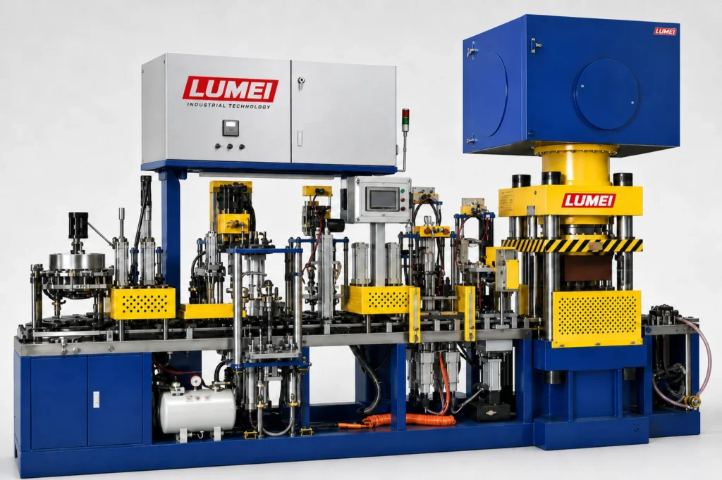
1. Define the purchasing scope with a product list
Separate near-term production from future plans. Record the following for each product.
| Product information | Machine or process items to check |
|---|---|
| Diameter, thickness and bore | Moulds, central locating components and forming space |
| Flat, depressed-centre or other shape | Forming surfaces, support and demoulding method |
| Mesh dimensions, layers and position between material layers | Mesh placement, feeding, positioning and inspection operations |
| Formulation or material-system reference | Feeding, material distribution and representative trial materials |
| Main sizes, order mix and shifts | Operating conditions and the basis for output assessment |
| Changeover combinations, frequency and existing tooling | Replacement parts, setting changes and interface compatibility |
Distinguish finished-product, pressed-blank and mould dimensions. They are not interchangeable. Identify missing drawings or samples, and do not include those products in the confirmed production scope yet.
2. Check pressing and demoulding capability after dimensional fit
A flat cutting disc and a depressed-centre grinding disc of the same diameter may require different forming surfaces, support or settings. Changes in thickness or bore also require a fresh check of filling space, central location, pressing and demoulding conditions.
Ask the supplier to use the product process and machine documentation to confirm the required pressing force, permissible effective stroke, opening clearance, demoulding travel, and compatibility with receiving and transfer operations. Hydraulic pressure readings and pressing force are not interchangeable. A screen setting alone cannot establish suitability.
Use the forming equipment catalogue for an initial shortlist, then confirm which tooling and optional mechanisms the proposal and price include. Check existing tooling interfaces, location, dimensions and drawing revisions. Changeable moulds do not mean that old moulds fit directly.
3. Translate reinforcement structure into an operation sequence
From the approved structure and process, list the actual sequence of component placement, layered filling, each mesh layer, pressing and demoulding. Identify manual, standard-machine and optional operations.
Check mesh diameter, bore, shape and supply condition against the proposed mechanism. Check whether later feeding and indexing retain the specified position. Review each layer separately; a single-layer trial does not establish multilayer suitability.
Automatic placement and mesh detection are separate capabilities. If detection is included, specify whether it checks presence, quantity, position or something else. Blank surface appearance alone cannot establish internal reinforcement conformity. Link abnormalities to the product, operation stage and sample number.
4. Compare heads, stations and output under common conditions
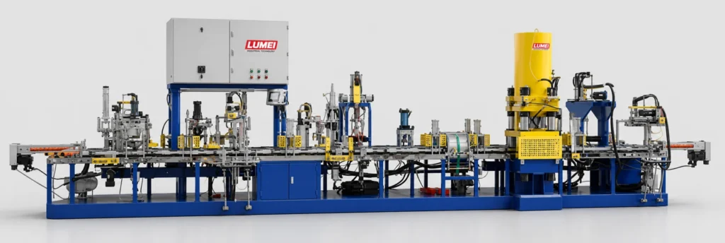
Press-head count, station count and product coverage describe different things. One does not directly determine the others. Confirm station functions from the machine sequence diagram.
For example, before comparing the two-head automatic push-type machine, 48–52 stations and the single-head automatic push-type machine, 54–58 stations, confirm that the target product falls within the confirmed scope of both proposals. Then assess them using the same product and agreed conditions.
| Comparison | Conditions to align or define for both proposals |
|---|---|
| Product and materials | Drawing revision, mesh structure, material batch and process requirements |
| Complete operating cycle | Scope covering feeding, mesh placement, pressing, demoulding and manual intervention |
| Output and quality | Same observation period and inspection method; distinguish blanks from accepted finished products |
| Changeover | Same product pair and timing scope for replacement, adjustment and production recovery |
Reference output supports initial discussion. More heads do not establish proportional output gains, and forming cycle time is not accepted finished-line output. For thickness troubleshooting, see the pressed-blank thickness control guide.
5. State what each trial product must verify
Use main products to assess continuous operation; dimensional boundary products within permitted machine limits to check tooling and motion space; different reinforcement structures to check operation coverage; and frequent changeover pairs to assess switching and recovery. Choose samples for the project. Do not explore machine limits by trial pressing.
Agree drawing and process revisions, material batches, tooling, sample quantities, operating arrangements, measurement methods and acceptance requirements before trials. Record production time, relevant mould or station IDs, interruptions, manual intervention, and parts or settings changed during changeovers.
Complete agreed curing and inspections on the samples. Acceptable blank dimensions alone do not establish finished cutting or grinding performance or applicable safety requirements. Define conditions and responsibilities for those evaluations separately.
6. Separate configuration compatibility from validation results
Configuration may be recorded as compatible as configured, additional tooling or mechanisms required, pending assessment, or outside scope. Record validation separately as not started, performed but evaluation incomplete, agreed checks passed, or nonconformities found. A product needing extra equipment may also be untested; these are not mutually exclusive.
The following is a fill-in example, not a customer case or a statement of machine capability. Enter actual dimensions, drawing and material references, and retain a separate record for each product.
| Example product | Configuration compatibility | Validation result | Record or next action |
|---|---|---|---|
| Main flat cutting disc | Pending assessment | Not started | Supply drawing, materials and mesh structure |
| Same diameter, different thickness or bore | Pending assessment | Not started | Check tooling, location, pressing and demoulding |
| Different reinforcement structure | Pending assessment | Not started | Check mesh sequence, mechanisms and inspection items |
Agreed checks passed applies only to the recorded product, configuration and evaluations. It does not mean every performance or compliance requirement passed. One product result does not automatically cover other structures.
What to prepare for a discussion with LUMEI
Prepare the product list, drawings or samples, material-system references, main sizes, target output and shifts, plus existing machine and tooling information. List future products separately to clarify quotation scope and unresolved items.
When arranging trial production and validation, agree records and evaluation conditions. For a complete line, use the cutting disc manufacturing solution to review mixing, forming, curing, inspection and packaging interfaces. The selection document should link each product to its configuration, validation results and outstanding items.
Compare the published forming configurations
Connect this guide’s selection questions with the documented product ranges and conditional reference outputs. Check a model against the actual drawing and trial conditions before treating it as suitable production equipment.
Related selection and quotation resources
Tell us about your manufacturing requirements
Discuss equipment, materials, process and delivery scope.
Submit project requirements →